
Function, Application and Selection
Closing an isolation valve does not necessarily make an instrument safe to remove.
A small volume of pressurised liquid or gas can remain trapped between the valve and the pressure gauge, transmitter, or manifold. Without a dedicated vent point, a technician may have to loosen a fitting to release it. This creates an uncontrolled discharge close to the technician’s hands and disturbs a connection that will later need to be remade.
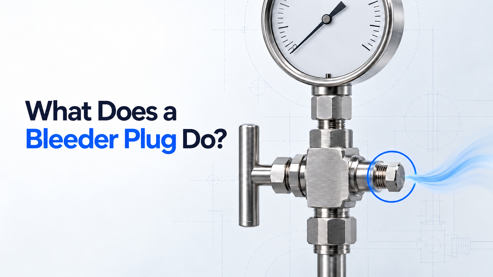
A bleeder plug provides a controlled point for releasing this residual pressure before an instrument is inspected, calibrated, or removed.
Why Pressure Remains After Isolation
An isolation or root valve separates the instrument from the process supply. It does not remove the fluid already present downstream of the valve.
Residual pressure may remain within:
- The pressure gauge or transmitter
- The instrument side of a manifold
- A gauge valve
- An impulse line
- Threaded adapters and internal cavities
A zero reading on the instrument does not always confirm that every part of the assembly has been depressurised. The gauge may be blocked, damaged, incorrectly calibrated, or isolated from pressure trapped elsewhere in the connection.
Safe maintenance therefore requires two separate actions: isolating the process and releasing the stored pressure.
How a Bleeder Plug Works
A bleeder plug is a compact instrumentation accessory installed in a threaded vent or drain port, normally downstream of the isolation valve and close to the instrument.
Its internal stem or screw seals against a seat. When carefully loosened, it opens a small passage through which trapped liquid or gas can escape. Tightening the stem closes the passage again.
A typical maintenance sequence involves:
- Closing the isolation valve.
- Positioning the required drainage or containment.
- Opening the bleeder plug slowly.
- Allowing the trapped pressure to discharge.
- Confirming that the discharge stops.
- Verifying depressurisation under the approved site procedure.
- Closing the plug before returning the assembly to service.
A short discharge followed by no further flow indicates that the trapped volume has been released. Continued discharge may indicate that the isolation valve is passing or has not been fully closed.
The bleeder plug does not provide process isolation. It works with the isolation valve by giving the trapped pressure a controlled exit.
Functions Within an Instrument Assembly
The primary role of a bleeder plug is depressurisation, but the same vent point can support several operational and maintenance activities.
Controlled pressure release
The plug allows pressure trapped between the isolation valve and instrument to be released without loosening the gauge, transmitter, or main connection.
Isolation verification
If fluid continues to discharge after the trapped volume should have emptied, the technician has an early indication that the upstream isolation may not be holding.
Draining residual liquid
In liquid service, the plug can help drain the instrument-side cavity before maintenance. Hazardous, hot, corrosive, or environmentally sensitive media must be contained or routed according to the plant procedure.
Calibration and testing
Some instrument arrangements allow test equipment to be connected through the vent port after the assembly has been safely isolated and prepared. This depends on the design and should only be done using an approved adapter and procedure.
Venting trapped gas
During filling or commissioning, a suitably positioned vent point can help remove unwanted air or gas from certain liquid-filled instrument connections.
Typical Applications
Bleeder plugs are commonly used with pressure gauges, pressure transmitters, gauge valves, manifolds, block-and-bleed arrangements, hydraulic systems, instrument panels, and calibration assemblies. They are particularly useful where maintenance teams need to remove or test pressure instruments without disturbing the primary process connection.
Applications can be found across oil and gas, chemical processing, petrochemicals, power generation, water treatment, pharmaceuticals, industrial automation, and other process industries.
Parflow Application Case: Improving Gauge Maintenance at a Chemical-Processing Facility
A chemical-processing customer approached Parflow with a recurring maintenance problem across several pressure-gauge installations.
The gauges were connected to liquid process lines through local isolation valves. Closing the valve separated each gauge from the process, but residual liquid and pressure remained trapped within the instrument-side cavity.
Because the existing assemblies did not have dedicated vent points, technicians had to loosen the gauge connection carefully to release this pressure before removing the instrument.
This made maintenance harder to control. The direction of discharge was unpredictable, the technician’s hands remained close to the release point, and the main threaded connection had to be disturbed before depressurisation could be confirmed. If an isolation valve was passing, the problem only became apparent after the connection had already been loosened.
Parflow’s assessment
Parflow reviewed the assembly layout, process media, pressure and temperature conditions, connection details, available port size, and maintenance requirements.
The review identified an unused instrument-side port where a bleeder plug could be incorporated without requiring a major modification to the surrounding piping.
Material and connection compatibility were evaluated because the plug would be exposed to the same process conditions as the gauge assembly.
The solution
Parflow supplied bleeder plugs configured for the customer’s connection and service requirements. The plugs were installed downstream of the isolation valves and close to the pressure gauges.
Under the revised maintenance procedure, technicians could close the isolation valve and open the bleeder plug slowly to release the trapped pressure through a known point. Once the discharge stopped and depressurisation was confirmed, the gauge could be removed.
If the discharge continued, the technician could identify a potentially passing isolation valve while the primary instrument connection remained closed.
The outcome
The revised arrangement gave the maintenance team a dedicated and repeatable depressurisation point.
It reduced the need to loosen gauge connections to release pressure, provided better control over the discharge location, and allowed isolation problems to be identified earlier. It also simplified gauge removal without requiring a substantial redesign of the existing installation.
The application showed how a small component, placed correctly within the assembly, could resolve a practical maintenance problem.
Bleeder Plug, Bleed Valve and Ordinary Plug
Although these components may occupy similar ports, they do not perform the same function.
An ordinary threaded plug closes an unused port. It does not provide a controlled venting mechanism and generally must be removed to open the port.
A bleeder plug seals the port while incorporating a small, controllable vent passage. Its compact construction makes it suitable for instrument connections where space is limited and venting is required occasionally.
A bleed valve performs a similar function but normally has a more recognisable valve body and operating stem. Depending on its design, it may provide easier operation, a larger outlet, or better discharge routing for frequently used vent points.
The appropriate choice depends on available space, operating frequency, process media, pressure, temperature, and discharge-handling requirements.
Selection and Installation Considerations
A bleeder plug should be selected as part of the complete instrument assembly rather than as an isolated accessory.
The plug’s pressure and temperature ratings must cover the maximum credible service conditions. Wetted materials must be compatible with the process media, particularly in corrosive, toxic, flammable, high-purity, or oxygen service. The thread form, size, and sealing method must match the receiving port. Similar-looking thread standards are not necessarily interchangeable.
Vent direction also matters. The discharge path should face away from personnel and nearby equipment. Applications involving hazardous media may require containment or a closed-drain arrangement rather than direct atmospheric venting.
A compact bleeder plug may suit occasional instrument maintenance. Where the vent point will be operated frequently, a dedicated bleed valve may be more appropriate.
Safe Operation
Bleeder plugs handle stored pressure and should only be operated by trained personnel under an approved isolation procedure.
Before opening the plug:
- Confirm the process line and media.
- Close the correct isolation valve.
- Provide the necessary containment or drainage.
- Wear the required personal protective equipment.
- Keep personnel clear of the vent direction.
- Open the plug slowly.
- Treat continuous flow as a possible isolation failure.
- Confirm depressurisation before loosening another connection.
The operating stem should not be completely removed unless the component design and approved procedure specifically require it.
For toxic, flammable, corrosive, or environmentally hazardous media, venting directly into the surrounding area may be unacceptable. Additional isolation, purging, or closed discharge handling may be required.
Conclusion
A bleeder plug provides a controlled way to release pressure trapped between an isolation valve and an instrument.
It supports depressurisation, drainage, isolation verification, and certain calibration activities without requiring the primary gauge or transmitter connection to be loosened first.
Its effectiveness depends on correct material selection, pressure and temperature compatibility, connection design, vent orientation, and operating procedure. When properly integrated into an instrumentation assembly, it can make routine maintenance more controlled and easier to verify.