
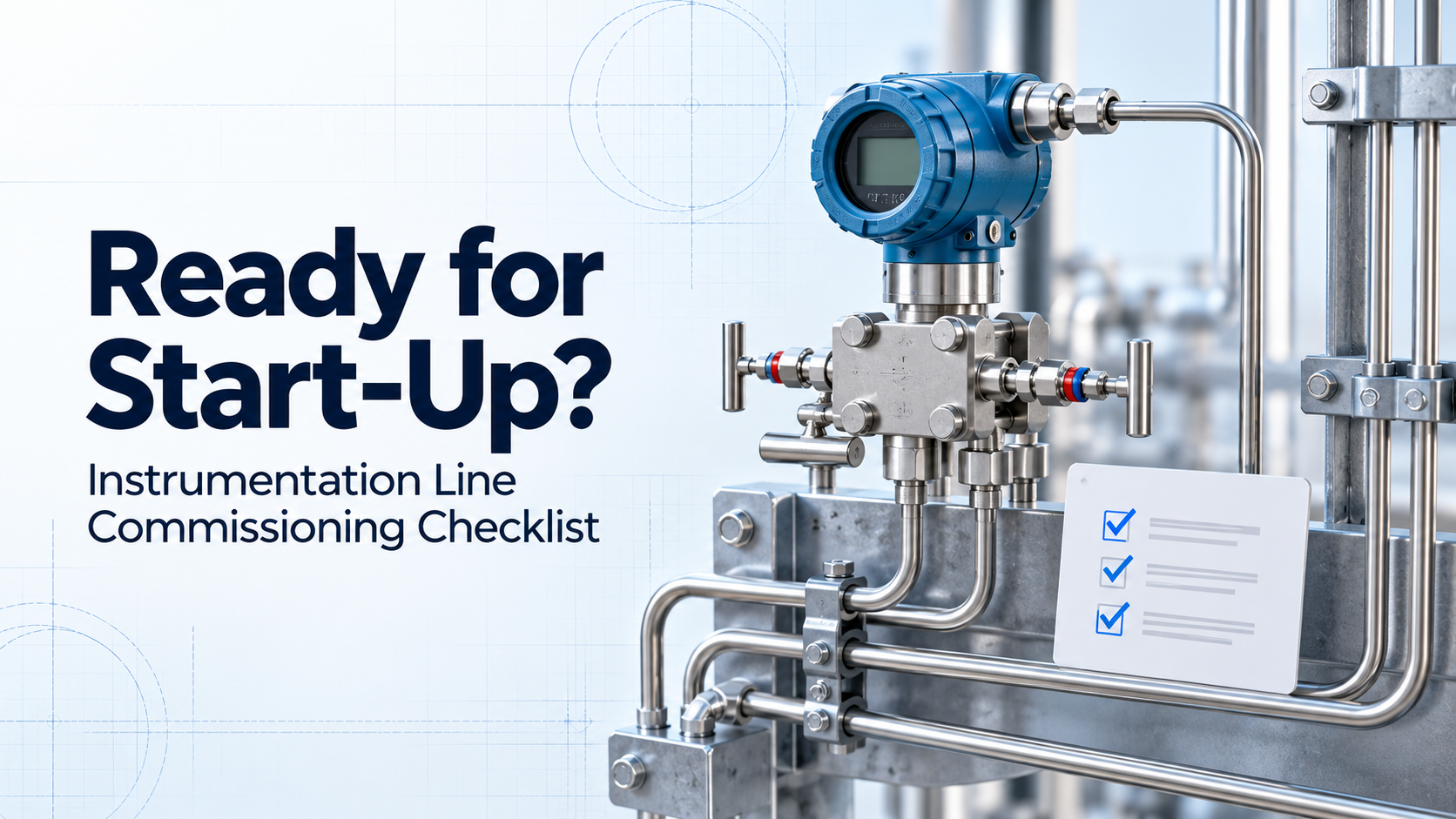
Commissioning is the point at which an instrumentation line moves from installation to live operation. By this stage, the tubing may be installed, the valves mounted, and the instruments connected, but that does not necessarily mean the line is ready for process conditions.
A connection that has not been properly tightened, an incorrectly positioned valve, residual debris inside the tubing, or an unverified instrument range can create unreliable readings, leakage, or delays during start-up. A structured pre-commissioning inspection helps identify these issues while the system can still be corrected safely.
The exact procedure will depend on the application, process media, plant requirements, and applicable standards. However, the following checks provide a practical foundation for most instrumentation lines.
Confirm the Line Against Approved Documents
Begin by confirming that the installed line matches the approved engineering documents.
Review the relevant:
- 1 Piping and instrumentation diagram
- 2 Instrument datasheet
- 3 Hook-up drawing
- 4 Line list
- 5 Instrument index
- 6 Isometric or layout drawing
- 7 Cause-and-effect documentation, where applicable
- 8 Inspection and test plan
- 9 Manufacturer’s installation instructions
Check that the instrument tag, service, process connection, line routing, valve configuration, and flow direction correspond with the approved design.
Any site modification should be recorded and approved before commissioning. If the physical installation differs from the latest drawing, the discrepancy should be resolved rather than treated as a minor field adjustment.
Verify Component Specifications
Every component in the instrumentation line should be suitable for the intended service.
Confirm the specification of:
1 Instrumentation valves
2 Manifolds
3 Tube fittings
4 Tubing
5 Pipe fittings
6 Adapters
7 Clamps and supports
8 Seals and packing
9 Pressure instruments
10 Drain and vent components
Verify the material grade, pressure rating, temperature rating, connection type, and media compatibility. The complete assembly is limited by its lowest-rated component, so an appropriately rated valve does not compensate for an unsuitable fitting, seal, or instrument.
Where material traceability is required, confirm that identification markings and supporting documentation are available and correspond with the installed components.
Inspect Tubing and Connections
The tubing installation should be checked across its entire route, not only at the instrument.
Look for:
1 Dents, scratches, flattening, or other tube damage
2 Bends that are too tight or distorted
3 Misaligned connections
4 Excessive mechanical stress
5 Unsupported lengths of tubing
6 Contact with sharp edges
7 Interference with nearby equipment
8 Inadequate clearance for maintenance
9 Incorrectly assembled fittings
10 Mixed or incompatible connection standards
Tubing should enter a fitting in alignment. It should not be pulled, forced, or bent into position through the connection. External stress can affect sealing performance and place unnecessary loads on the valve or instrument.
Clamps and supports should control vibration without damaging the tubing. The installation should also allow technicians to operate valves, access fittings, remove the instrument, and perform future maintenance.
Check Routing, Slope, and Drainage
Instrumentation line routing affects measurement accuracy as well as maintainability.
Depending on the service, the line may require a continuous slope to prevent unwanted liquid or gas from becoming trapped. Poor routing can create pockets in which condensate, vapour, sediment, or air accumulates.
Confirm that:
1 The routing suits the process media.
2 The required slope has been maintained.
3 High and low points have been addressed.
4 Vents and drains are accessible.
5 The line is protected from avoidable heat exposure.
6 Freezing or condensation risks have been considered.
7 The instrument is installed in the intended position.
The correct arrangement depends on whether the service involves gas, liquid, steam, or another process medium. Project drawings and instrument manufacturer instructions should determine the final routing.
Confirm the Line Is Clean
Debris left inside an instrumentation line can obstruct a small flow path, damage a valve seat, contaminate the process, or prevent an instrument from responding correctly.
Before commissioning, confirm that:
1 Open tube ends were protected during installation.
2 Cutting debris and metal particles have been removed.
3 The line has been cleaned or flushed as specified.
4 The cleaning medium is compatible with the system.
5 Cleaning residue has been removed.
6 The line has been drained or dried where required.
7 Vents, drains, and small passages are clear.
Flushing should follow an approved procedure. Sensitive instruments may need to be isolated or removed during the process, depending on the flushing pressure, medium, direction, and contamination risk.
Impulse lines deserve particular attention because small passages can become blocked by material buildup or freezing, preventing the instrument from responding correctly to process changes.
Check Every Valve Position
Incorrect valve alignment is a common source of start-up problems. A closed isolation valve can prevent the instrument from sensing the process, while an open vent or drain can release process media when the line is pressurised.
Inspect each valve and confirm its required pre-start position.
Depending on the arrangement, this may include:
1 Root isolation valves
2 Manifold block valves
3 Equalising valves
4 Vent valves
5 Drain valves
6 Bleed valves
7 Bypass valves
For a manifold, follow the approved operating sequence rather than assuming that every valve should be open or closed. The correct position depends on the instrument, manifold configuration, and commissioning stage.
Valve handles should move correctly, remain accessible, and clearly indicate their position where the design permits.
Complete Pressure and Leak Testing
The instrumentation line should undergo the required pressure and leak tests before process introduction.
Before testing, define:
1 Test boundaries
2 Test medium
3 Test pressure
4 Hold time
5 Acceptance criteria
6 Components included in the test
7 Instruments that must be isolated or removed
8 Method of depressurisation
9 Required safety controls
Never expose an instrument, valve, fitting, or accessory to a test pressure above its allowable rating. If the test pressure for the adjoining process piping exceeds the instrument assembly rating, the lower-rated components must be protected according to the approved procedure.
During the test, inspect every connection, valve stem, body joint, vent, and drain. A line should not be approved solely because it holds pressure at the test source. The complete test boundary must be inspected, and the results should be documented.
After testing, release pressure in a controlled manner and restore all temporary connections, blinds, plugs, or test equipment to the required operating configuration.
Verify Instrument Readiness
The mechanical line and the connected instrument should be treated as one measurement system.
Confirm that the instrument has:
1 The correct tag number
2 The correct measurement range
3 The required calibration status
4 Suitable engineering units
5 Correct zero and span settings
6 Correct electrical or pneumatic connections
7 Appropriate environmental protection
8 Accessible vents and drains
9 Required certificates and records
For smart instruments, verify the configured range, output, damping, alarm behaviour, and communication settings where applicable.
A calibrated instrument can still provide an incorrect process reading if its impulse line is blocked, leaking, improperly routed, or incorrectly valved. Mechanical and instrument checks should therefore be completed together.
Perform Loop and Functional Checks
A loop check confirms that the signal travels correctly from the field instrument to the receiving control or monitoring system.
Depending on the application, verify:
1 Field indication
2 Control-room indication
3 Signal scaling
4 Tag identification
5 Alarm setpoints
6 Trip functions
7 Valve response
8 Signal direction
9 Communication status
10 Fail-safe behaviour
Any bypasses, overrides, or inhibited alarms used during testing should be recorded and removed through an authorised process before normal operation.
Functional testing should confirm the behaviour of the complete loop rather than only the response of the individual instrument.
Introduce Process Conditions Gradually
Once the inspection and testing stages are complete, process pressure should be introduced according to the approved start-up procedure.
During initial pressurisation:
1 Open valves in the specified sequence.
2 Increase pressure gradually.
3 Monitor every connection for leakage.
4 Observe the instrument response.
5 Check for unstable or unexpected readings.
6 Listen for vibration or abnormal flow noise.
7 Confirm that supports remain secure.
8 Stop if the system behaves unexpectedly.
Gradual pressurisation gives the commissioning team time to identify an issue before the line reaches full operating conditions.
After the system stabilises, recheck the valve configuration and confirm that vents, drains, and test connections are correctly closed or secured.
Complete the Commissioning Records
Commissioning is not complete until the supporting records have been updated.
The final documentation may include:
1 Inspection checklist
2 Pressure-test record
3 Leak-test result
4 Calibration certificate
5 Loop-check sheet
6 Valve-position record
7 Punch-list closure
8 Material traceability documents
9 Approved site modifications
10 As-built drawings
11 Commissioning sign-off
Accurate records provide evidence that the line was inspected and tested. They also give maintenance teams a reliable reference for future troubleshooting, isolation, and replacement work.
A Practical Pre-Commissioning Checklist
Before placing an instrumentation line into service, confirm that:
1 The installation matches the approved drawings.
2 Component materials and ratings suit the service.
3 Tubing is correctly routed, aligned, supported, and undamaged.
4 Connections have been assembled and inspected correctly.
5 Required slopes, vents, and drains are in place.
6 The line is clean and free from obstruction.
7 Valves are in the correct pre-start positions.
8 Pressure and leak testing has been completed.
9 The instrument is calibrated and correctly configured.
10 Loop and functional checks have passed.
11 Temporary test equipment and bypasses have been removed.
12 Records and as-built documents have been completed.
Conclusion
Instrumentation-line commissioning should verify the complete path between the process and the instrument. Component selection, tubing installation, cleanliness, valve alignment, testing, calibration, and documentation all influence whether the final measurement can be trusted.
A disciplined pre-commissioning check helps detect installation errors before they become leaks, unreliable readings, or start-up delays. It also gives operations and maintenance teams a clear, documented basis for placing the line into service.