
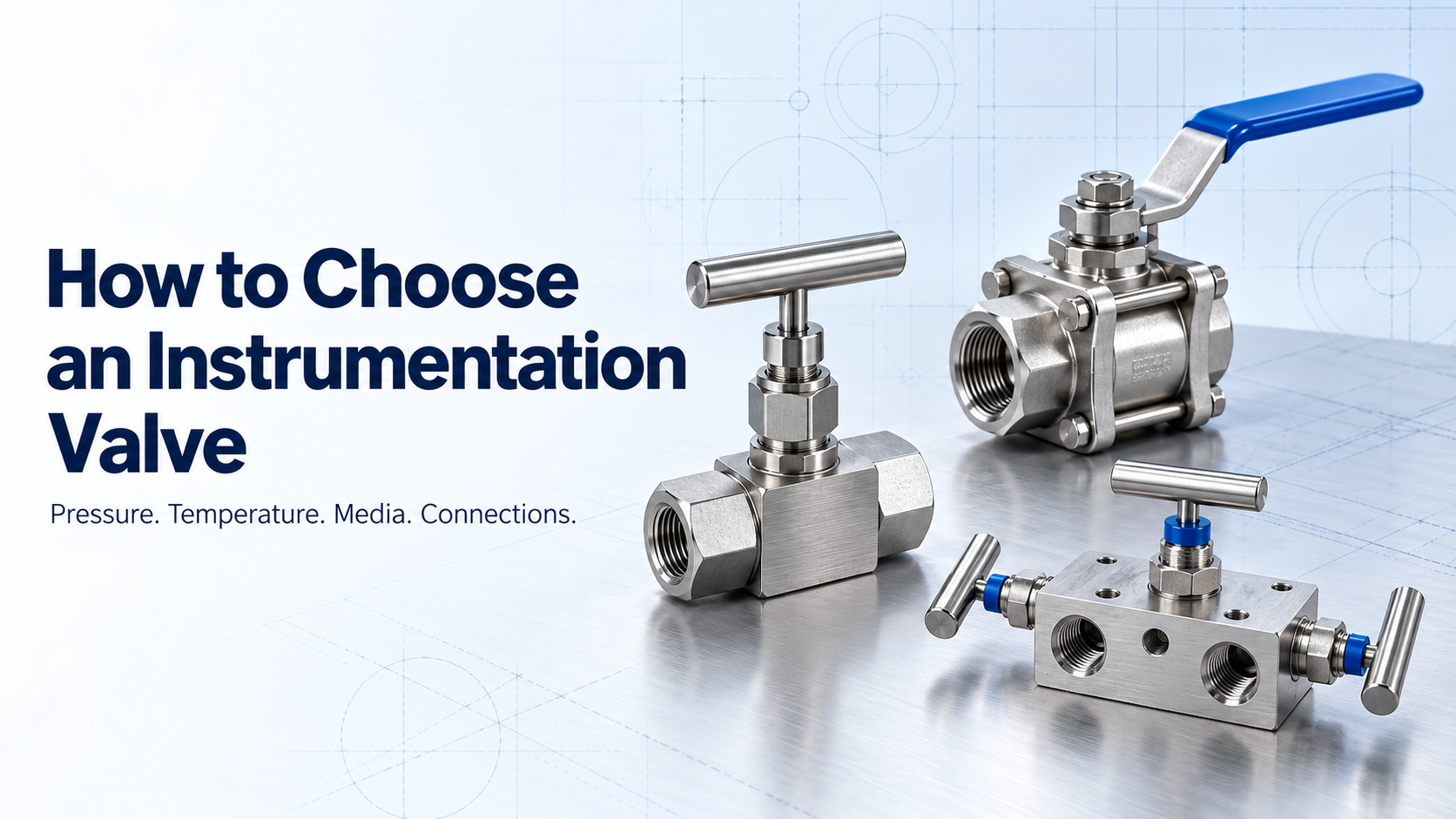
Instrumentation valves control, isolate, vent, or equalise process media within measurement and control systems. Although these components are relatively small, selecting the wrong valve can contribute to leakage, inaccurate measurements, difficult maintenance, and unplanned downtime.
A suitable valve must be evaluated as part of the complete system rather than selected only by its nominal size or pressure rating. Process conditions, media characteristics, connection requirements, operating frequency, and installation environment all influence whether a valve will perform reliably throughout its service life.
1 Define the Valve’s Function
The selection process should begin with a clear understanding of what the valve needs to do.
Common instrumentation valve functions include:
1 Isolating a pressure instrument from the process
2 Regulating or metering the flow of process media
3 Venting or bleeding trapped pressure
4 Equalising pressure across an instrument
5 Providing multiple isolation points
6 Allowing an instrument to be calibrated or removed safely
7 Directing flow between different process lines
Once the required function is established, the appropriate valve design becomes easier to identify.
Needle Valves
Needle valves use a tapered stem to provide controlled flow adjustment. They are commonly used for flow regulation, instrument isolation, sampling, and applications where gradual opening is required.
Ball Valves
Ball valves provide rapid shutoff through quarter-turn operation. They are generally suited to applications requiring dependable isolation with minimal flow restriction in the fully open position.
Manifold Valves
Manifolds combine multiple isolation, equalising, and venting functions within a compact assembly. Two-valve, three-valve, and five-valve manifolds are frequently used with pressure gauges, pressure transmitters, and differential-pressure instruments.
Double Block and Bleed Valves
Double block and bleed configurations provide two isolation barriers with a bleed point between them. They are used where enhanced isolation, pressure verification, or a reduction in potential leak paths is required.
The valve type should reflect the intended function. A valve designed primarily for isolation may not provide the flow control required for throttling, while a regulating valve may not offer the operating speed of a quarter-turn ball valve.
2 Determine the Maximum Working Pressure
Every valve must be rated for the pressure conditions it will encounter. Selection should account for more than the system’s normal operating pressure.
The assessment should include:
1 Normal operating pressure
2 Maximum allowable working pressure
3 Start-up and shutdown conditions
4 Pressure surges and pulsation
5 Test pressure
6 Differential pressure across the valve
7 Potential pressure trapped inside the assembly
The pressure rating of a valve can depend on its body material, seat or packing material, connection type, temperature, and design. A stated maximum pressure should therefore be checked against the complete product rating rather than considered in isolation.
High-pressure applications may require specialised valve bodies, suitable stem designs, compatible fittings, and carefully controlled installation practices. Every component within the assembly should be suitable for the same operating conditions. The pressure capability of a system is limited by its lowest-rated component.
3 Account for Operating Temperature
Temperature can affect the strength of the valve body, the performance of the seat and packing, and the behaviour of the process media.
When defining the required temperature range, consider:
1 Normal process temperature
2 Minimum and maximum operating temperature
3 Ambient temperature
4 Start-up temperature
5 Cleaning or steam-out temperature
6 Rapid temperature changes
7 Heat transferred through connected piping or tubing
Pressure and temperature ratings are related. A valve may have a lower allowable pressure at elevated temperatures because material strength and sealing performance can change as temperature increases.
Low-temperature applications also require careful evaluation. Some materials may lose toughness, while seals and lubricants can behave differently under cold conditions. Pressure and temperature should always be reviewed together using the manufacturer’s published data.
4 Verify Media Compatibility
The valve body, stem, seats, seals, packing, and any other wetted parts must be compatible with the process media.
Important media characteristics include:
1 Chemical composition
2 Corrosiveness
3 Toxicity
4 Flammability
5 Viscosity
6 Presence of moisture
7 Presence of suspended solids
8 Tendency to crystallise or solidify
9 Required cleanliness
10 Gas or liquid service
Material selection should be based on the actual process conditions. A material that performs well with a chemical at one concentration or temperature may not be suitable under different conditions.
For corrosive, hazardous, or high-purity media, the evaluation may also need to consider surface finish, potential contamination, fugitive emissions, internal volume, and the compatibility of non-metallic sealing materials.
Where the process composition can vary, the most demanding credible operating condition should guide the selection.
5 Choose the Appropriate Connection Type
The valve must integrate correctly with the tubing, piping, instrument, or equipment around it. Connection selection affects installation, maintenance, leakage risk, and overall assembly size.
Common connection options include:
1 Tube ends
2 Female threaded ends
3 Male threaded ends
4 Flanged connections
5 Mixed inlet and outlet connections
6 Application-specific connections
Tube fittings can provide compact connections for instrumentation tubing when they are correctly selected and installed. Threaded connections are widely used, but the thread form, size, sealing method, and installation procedure must match the system requirements.
The following details should be confirmed before specifying a connection:
1 Tube outside diameter or nominal pipe size
2 Thread type and pitch
3 Male or female orientation
4 Required sealing method
5 Available installation space
6 Need for removal or repeated maintenance
7 Compatibility with existing equipment
Similar-looking threads are not necessarily interchangeable. Combining incompatible thread standards can damage components and prevent a reliable seal.
Reducing the number of adapters and separate connections can simplify installation and decrease the number of potential leakage points. However, any integrated arrangement must still provide suitable access for operation, inspection, and maintenance.
6 Consider How Frequently the Valve Will Operate
A valve used for occasional instrument isolation has different operating demands from one adjusted several times during every shift.
Consider:
1 Expected number of operating cycles
2 Manual or automated operation
3 Required opening and closing speed
4 Need for precise adjustment
5 Torque required to operate the valve
6 Risk of accidental operation
7 Accessibility for the operator
8 Maintenance and inspection frequency
For frequent operation, stem design, handle arrangement, seat durability, and operating torque become particularly important. A valve located in a difficult-to-access area may require a different handle, mounting arrangement, or operating method.
The intended operating procedure should also be clear. Using an isolation valve for continuous throttling, for example, may cause wear if the valve was not designed for that service.
7 Review the Installation Environment
Conditions outside the valve can be as important as the process conditions inside it.
The installation review should account for:
1 Vibration
2 Outdoor exposure
3 Humidity and corrosion
4 Offshore or marine conditions
5 Dust and contamination
6 Limited installation space
7 High or low ambient temperatures
8 Nearby heat sources
9 Accessibility for inspection
10 Tubing loads and misalignment
Vibration can affect tubing connections, valve components, and connected instruments. Adequate tube support and careful routing may be necessary to reduce stress on the valve.
The valve should not be used to force misaligned tubing or piping into position. External loads can affect sealing performance and shorten component life. Sufficient clearance should also be provided for handle movement, connection tightening, inspection, and future replacement.
8 Evaluate Leakage and Sealing Requirements
The acceptable leakage level depends on the application and the media being handled. Systems carrying hazardous, flammable, expensive, or high-purity media may require more stringent sealing performance.
Evaluation points include:
1 Internal seat leakage
2 External leakage
3 Stem sealing
4 Fugitive-emission requirements
5 Allowable pressure loss
6 Required testing method
7 Frequency of inspection
8 Consequences of leakage
The valve design alone does not determine system integrity. Correct assembly, suitable tubing, compatible fittings, proper tightening, adequate support, and controlled commissioning are equally important.
9 Confirm Materials, Testing, and Documentation
For critical applications, product selection should include a review of the required quality and traceability documentation.
Depending on the project, this may include:
1 Material specifications
2 Material test certificates
3 Pressure or functional test records
4 Dimensional inspection
5 Product identification and traceability
6 Cleaning requirements
7 Inspection and test plans
8 Applicable industry standards
9 Project-specific documentation
These requirements should be discussed before ordering. Adding documentation or specialised testing after manufacturing may cause delays or may not be possible for an already completed product.
Information to Provide When Requesting a Valve
A complete application enquiry helps the manufacturer recommend a suitable product. Wherever possible, provide:
1 Required valve function
2 Valve type
3 Process media
4 Normal and maximum pressure
5 Minimum and maximum temperature
6 Required body and sealing materials
7 Inlet and outlet connection details
8 Flow or orifice requirements
9 Expected operating frequency
10 Installation environment
11 Applicable standards
12 Testing and documentation requirements
13 Quantity and delivery requirements
If any operating condition is uncertain, it should be identified during the selection process rather than assumed.
Conclusion
Selecting an instrumentation valve requires a complete review of its function, pressure, temperature, media, connections, operating pattern, and installation environment. Focusing on only one parameter, such as nominal size or maximum pressure, can overlook conditions that directly affect sealing performance, service life, and maintainability.
A well-defined application allows the valve, materials, and connection arrangement to be evaluated as one system. This supports safer operation, more dependable measurements, and fewer problems during installation and maintenance.